
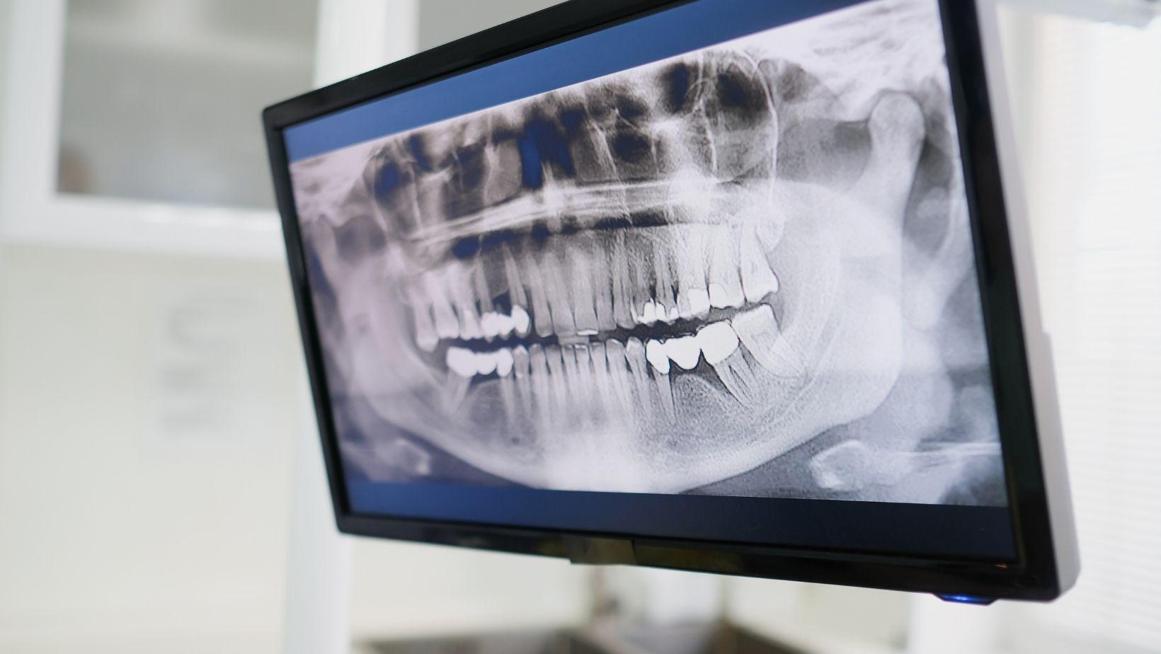
Dental implants require more than a visual examination. X-rays and three-dimensional imaging show the height, width, and shape of your jawbone while locating nearby structures such as nerves and sinuses. This kind of detailed imaging is standard practice for dental implants in Salt Lake City, UT, helping ensure the treatment plan accounts for your unique anatomy.
Imaging helps your dental team select an implant position, size, and angle that fit your anatomy and support safe, stable treatment. Panoramic and periapical X-rays provide useful views.
Cone beam computed tomography (CBCT) supplies detailed cross-sectional images when your case requires three-dimensional planning. Digital planning and guided surgery translate imaging data into precise placement.
Post-placement images help your dental team monitor healing, bone levels, and implant stability over time.
Imaging Tools Used in Implant Planning
You use imaging to measure available bone and identify nearby anatomical structures. Imaging also helps plan the implant’s size, position, and angulation.
Digital scans help you transfer the plan accurately to the surgical and restorative stages.
Digital X-Rays
Digital periapical and panoramic X-rays provide an initial assessment of your teeth, jaw, and supporting bone. Periapical images show the proposed implant site in greater detail, including the roots of adjacent teeth and localized bone levels.
Panoramic images cover both jaws and help identify missing teeth, retained roots, impacted teeth, and broad bone or sinus concerns. These images use lower radiation doses and can be captured and reviewed quickly.
Conventional X-rays compress three-dimensional anatomy into two dimensions, so they cannot reliably show bone width or the exact position of structures from the cheek-to-tongue direction. Your dentist may use digital X-rays for an initial evaluation, follow-up checks, or cases with straightforward anatomy.
If the site appears narrow, irregular, or close to the mandibular nerve or sinus, additional three-dimensional imaging may be appropriate.
Cone Beam Computed Tomography
Cone beam computed tomography (CBCT) produces a three-dimensional view of your jaw. It allows your dentist to measure bone height, width, and angulation and to locate structures such as the mandibular canal, mental foramen, nasal cavity, and maxillary sinus.
Your clinician can use CBCT data to assess whether the planned implant fits within the available bone and whether bone grafting or sinus augmentation might be necessary. The scan can also support computer-guided surgery and the design of a surgical guide.
CBCT does not replace a clinical examination. Your dentist should request it when the additional information will affect treatment.
Radiation exposure varies by device and scan size. The clinician should use the smallest field of view and lowest suitable dose that provide adequate diagnostic detail.
Intraoral Scanners And Digital Models
An intraoral scanner records the shape and position of your teeth, gums, and bite as a digital model. Unlike physical impressions, it creates an immediate three-dimensional file that your dentist can inspect, edit, and combine with other records.
Your dentist may merge the scan with CBCT data to align the planned implant with the future crown or denture. This approach supports prosthetically driven planning.
Prosthetically driven planning places the implant according to the restoration’s position, function, and appearance rather than bone anatomy alone. Digital models also help design surgical guides, temporary restorations, and customized abutments.
Scanning accuracy can decrease when saliva, blood, reflective surfaces, or large toothless areas interfere with image capture. Your dentist may verify the digital model against clinical findings and other records.
Anatomical Measurements That Determine Implant Position
Imaging lets you measure available bone, locate structures that require protection, and assess the space between neighboring roots. These measurements help you select an implant that fits the site and position it with sufficient clearance for bone support, surgical safety, and restoration design.
Bone Height, Width, And Density
You need to measure bone height from the planned implant platform to the nearest limiting structure, such as the maxillary sinus or inferior alveolar canal. Measure buccolingual width at several levels because the ridge may narrow toward its crest.
CBCT provides cross-sectional views that reveal ridge shape, undercuts, angulation, and defects that a two-dimensional image can hide. Bone density also influences implant planning, although imaging estimates do not replace clinical assessment.
Lower-density bone may require a narrower or longer healing strategy. Dense cortical bone can limit drilling flexibility.
Nerve Pathways And Sinus Cavities
You must identify the inferior alveolar canal, mental foramen, and anterior loop before planning implants in the posterior or premolar mandible. Measure the distance from the proposed implant to these structures and maintain a safety margin appropriate to the imaging quality, surgical technique, and clinical circumstances.
CBCT can show canal course variations that panoramic imaging may not define reliably. In the posterior maxilla, assess the sinus floor, septa, membrane condition, and available vertical bone.
Sinus expansion can reduce implant height, while a tilted sinus floor can change the ideal implant axis. If the measurements do not provide adequate clearance, you may need a shorter implant, an altered position, or bone augmentation.
Root Positions And Adjacent Tooth Spacing
Measure the mesiodistal space between neighboring roots, not only the visible crown space. Root divergence, convergence, and proximity to the planned osteotomy can restrict implant diameter and angulation.
CBCT helps you evaluate these relationships in three dimensions, particularly when roots overlap on a panoramic or periapical image. You should also assess the distance from the implant to adjacent roots and determine whether the restorative emergence profile will fit the available space.
A digitally planned implant must correspond with the final crown position. Check for retained roots, impacted teeth, resorption, and periapical pathology before surgery.
Digital Planning And Guided Surgery
You use three-dimensional imaging, digital impressions, and planning software to position implants according to available bone and the intended restoration. A printed surgical guide then transfers that plan to the mouth.
Verification tools help you confirm placement during treatment.
Virtual Implant Placement
You begin by combining cone-beam computed tomography (CBCT) data with an intraoral scan or a digitized dental cast. CBCT shows bone height, width, density, and important structures such as the mandibular canal, nasal cavity, and maxillary sinus.
The surface scan records teeth, gingiva, and occlusal relationships. Planning software merges these datasets into a three-dimensional model.
You can then position a virtual implant according to the planned crown, bridge, or denture rather than bone availability alone. The software lets you evaluate implant angulation, depth, spacing, emergence profile, and restorative clearance.
You should verify the registration of each dataset because alignment errors can affect the entire plan.
Surgical Guide Fabrication
After you approve the virtual plan, the software generates a guide design that contains sleeves or an integrated guidance system. The guide may rest on teeth, mucosa, or bone.
Tooth-supported guides often provide stable positioning when enough healthy teeth remain. Mucosa-supported and bone-supported designs require careful control of fit and movement.
A laboratory or printer produces the guide from the approved digital file. You should check its seating, stability, sleeve position, and access to the surgical site before treatment.
The guide improves transfer of the planned implant position, but it does not eliminate clinical judgment. Limited mouth opening, guide deformation, scanning errors, and inadequate seating can reduce accuracy.
Real-Time Verification During Placement
Guided surgery controls the drill path, but you still verify the guide’s fit and the surgical sequence at each stage. Before drilling, inspect the guide visually and confirm complete seating against the registered teeth, mucosa, or exposed bone.
If the guide rocks or fails to seat fully, stop and identify the cause rather than proceeding. You can use depth markings, drill stops, and indexed components to control osteotomy depth and angulation.
After placement, a periapical radiograph can assess the implant in relation to adjacent roots or other critical structures. In selected cases, an additional CBCT scan or intraoral scan supports three-dimensional verification.
Post-Placement Imaging And Long-Term Monitoring
Post-placement imaging helps you verify implant position, evaluate bone healing, and establish a reference for future comparisons. It also supports early detection of bone loss, component problems, and other changes that may affect implant function.
Confirming Implant Alignment
After placement, a periapical radiograph can document the implant’s position in relation to the adjacent teeth and surrounding bone. You can use it to assess the implant’s apparent angulation, depth, and relationship to structures such as the mandibular canal or maxillary sinus.
Two-dimensional images may not show every spatial relationship accurately. A panoramic radiograph can provide a broader view of multiple implants and the jaws.
If the implant position remains unclear, or if the site involves complex anatomy, cone-beam computed tomography (CBCT) may provide more detailed three-dimensional information. Because CBCT exposes you to more radiation than routine dental radiographs, your clinician should use it when the additional information will change diagnosis or treatment.
Assessing Osseointegration
Imaging cannot prove osseointegration by itself. Your clinician combines radiographic findings with clinical evidence, including implant stability, absence of pain or mobility, healthy surrounding tissue, and proper function.
Radiographs can show whether the implant remains closely associated with the surrounding bone and whether a persistent radiolucent line appears around it. Comparison with the immediate postoperative image helps your clinician evaluate crestal bone levels and detect progressive changes.
Standardized periapical images, using a consistent angle and positioning technique, improve the reliability of these comparisons.
Detecting Future Complications
During maintenance visits, your clinician may use periapical radiographs to monitor marginal bone levels, particularly when clinical findings indicate a concern.
Increasing bone loss, bleeding on probing, swelling, suppuration, pain, or implant mobility can indicate peri-implant disease or mechanical problems.
Imaging may also help identify fractured components, an altered implant position, excess cement, or bone changes near critical structures.
If symptoms or conventional radiographs do not explain the problem, CBCT may be appropriate.
You should not receive routine scans without a clinical reason.
Your imaging schedule should reflect your symptoms, risk factors, implant history, and examination findings.